Chapter 1 - "The Alpmic Arrives" by CARL BLARE
When I ran a medium sized recording studio my objective was to capture the voice with extreme clarity, and I spent a fortune on microphones but had yet to be satisfied. I began running all kinds of experiments.
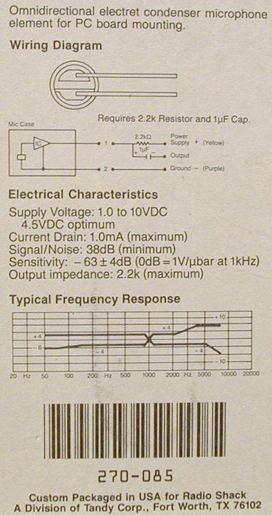
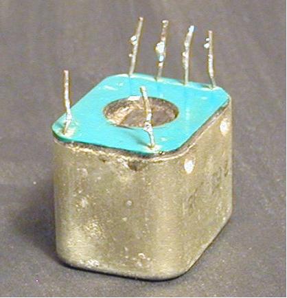
I wondered what could be the difference between a $1,000 AKG condenser from Austria and a $1.54 electret capsule from Radio Shack. The capsule I chose was Part No. 270-085. What I discovered was astounding!
Whereas the AKG made a symphony orchestra perfectly distinct from a distance of about 20-feet away, it did poorly on voice recorded close up. Conversely the Radio Shack capsule did unexpectedly well on voice, but sounded tinny on orchestra. That's when I started playing seriously.
The "Alpmic" was named for our recording business, "Alpine Recording Service." The first real-world test came in the mid 90s when an audio book reader agreed to test an early version of my mic. She said, "I have never sounded so good before!"
My Alpmic file became loaded with notes and drawings as I went through various test models.
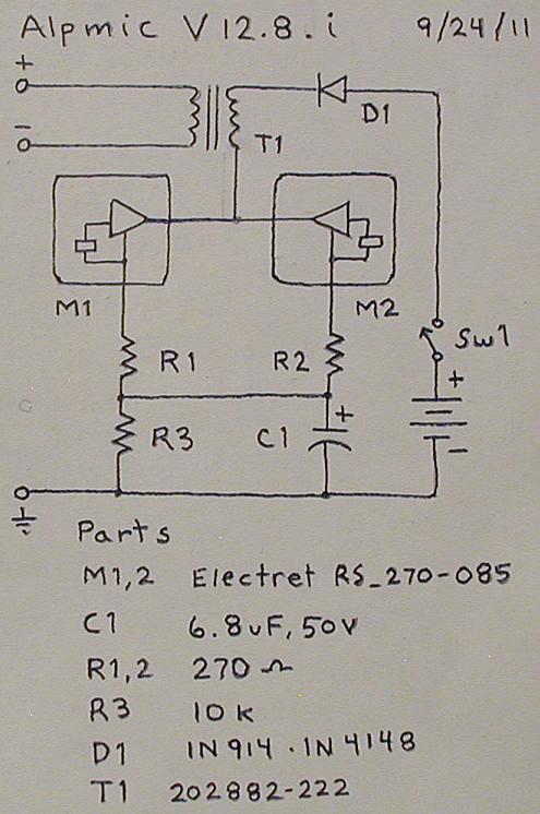
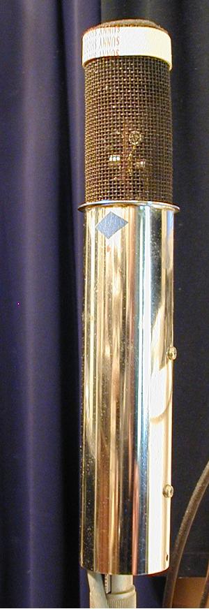
The version shown now is V 12.8.i, in service from 9/24/11 to 8/5/13, when I removed it for cleaning and photo grabbing for this "How To" demonstration on the ALPB website.
There is so much detail I want to share with you that I hope MRAM 1500 will allow me to build on this presentation a chapter at a time.
To start, here are photos and a schematic of V 12.8.i.
The ALPMIC
by CARL BLARE
Chapter 2 - "Coupling"
To bring the low-level output of a microphone up to line level requires a pre-amp, and can be complicated by several factors. Let's pick one of those factors to start with: balancing.
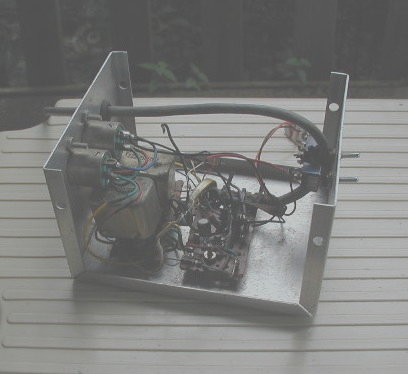
The professional mic input is typically an XLR balanced connector, but a simple electret mic capsule is un-balanced. One solution is a transformer, and I tried one from the spare-parts box which cost 25-cents from a surplus store, and it worked. Unfortunately, as you'll see in the photo, the transformer contains no brand, only the number 202882-222, but serves as a step-down transformer.
A second factor that is very important, in my opinion, is impedance matching, an art which is viewed in a number of different ways by different people. In the U.S. the common mic impedance is "150-ohms"; although in the past "50-ohms" was not uncommon. But in Europe "200-ohms" is the standard, and many European microphones are purchased in the U.S. The mix-up is even crazier because consumer equipment has odd-ball mic impedances on mixer and other recording inputs, such as "1k", "10k", "50k" and my Radio Shack mixer with "600-ohms."
Fortunately I came into possession of a white paper on microphone input impedance printed by Neumann of Germany and distributed in the U.S. by Gotham Audio, titled - "THE CONNECTION OF NEUMANN CONDENSER MICROPHONES TO THE INPUTS OF AMERICAN TYPE PREAMPLIFIERS." This paper served as my guide for selecting the parts used in this published version of my Alpmic.
Chapter 3 - "What It Is"
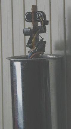
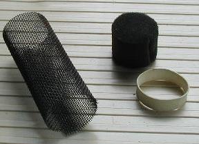
Let me tell you what the pictures show. The picture that shows the screen removed and the capsules exposed is laid on its side with a thunderstorm approaching out on the front porch. At the very top two electret capsules are bundled side-by-side by a black tie-wrap poked through the holes of a "peg-board" type circuit card, which serves to insulate the two metal cases of the respective capsules, since the cases are wired to the negative voltage leads and these are separate parts of the circuit and should not be shorted together.
Two other capsules are seen lower down, but they are not part of the discussion and were never put to use. More on that later.
Of the two operational capsules, one points toward you (the announcer) and the other points away from you (even though you are still the announcer). The capsules are mixed together in the circuit and form an omni-directional pattern, so that you could have an interview guest on the other side and use a single Alpmic to hear you both. The omni-directional pattern also "opens" the overall sound, so that the entire ambience of the recording space is heard, which appeals to me but may not appeal to everyone, especially if there is unwanted noise in the environment.
The chrome pipe enclosure was purchased from a hardware store. Its intended purpose is that of a sink drain pipe. The size, shape, color and cost were a perfect fit for the ALPMIC.
Originally I was going to develop a Swiss-jack-knife microphone with mid/side stereo, cardioid and omni, all switch selectable, but only the omni part got done, so all the redundant parts do nothing, including a second transformer and XLR plug in the control box.
When first built, the control box was neat and perfect, but with many changes over the years it has gotten very messed-up and needs to be sent to the hospital for corrective surgery.
The diode was added at the advice of RFB to help solve a problem of "self-popping" that was being randomly generated. He thought perhaps the two capsules were loading into one another and causing the noise, and indeed the diode made it stop.
The box houses a 9-Volt DC battery, but I intend to build a regulated power supply, because I believe (subjectively) that the sound of the microphone changes as the battery life dwindles.
The ALPMIC
Click here for an AUDIO CLIP of the ALPMIC in operation. This clip is from one of Carl's programs using the ALPMIC for his announcing.
SIDEBAR NOTE
THE CONNECTION OF NEUMANN CONDENSER MICS TO THE
INPUTS OF AMERICAN TYPE
PREAMPLIFIERS
1.) THE IMPEDANCE SITUATION:
The preamplifiers found in NEUMANN condenser microphones are
designed to
operate solely as voltage amplifiers with unterminated output. When set for
a source impedance of 50 or 200 ohms they should look into a load of a magnitude
at least five times this value, or a minimum of 250 ohms or
1000 ohms. Non-linear distortion will increase rapidly for high sound pressure
levels if this is not strictly observed. This same problem concerns ALL condenser
microphones no matter whose manufacture, but many firms ignore it in order
to make the condenser microphone more acceptable to the general market. We
at GOTHAM AUDIO feel that imperfections of even a few dB in the microphone's
response as a result
of improper application is of the greatest concern when applied to a product
which is engineered to fractions of a decibel.
American preamplifiers generally use at their input an unterminated
input transformer whose input impedance is highly frequency dependent. Should
one now select, as is usually the case in the U.S., the nominal
input impedance equal to the source impedance of the microphone, an inadmissible
loading of the microphone will occur in any case at the high frequency end,
and usually also at the very low frequencies.
Should one, to avoid this problem, choose a nominal input impedance
which is higher than the source impedance of the microphone, then a rising
characteristic at the high frequencies of several decibels will result. This
is due to the fact that the unterminated input transformer requires that the
impedance of the source feeding it be equal to the nominal input impedance.
A source impedance of the preceding device which is too low results (due to
stray resonances in the transformer) in
a rise at high frequencies, while a source impedance too large will produce
a droop at the high end.
The ALPB © 2013
Last Update - Friday, 16-Jun-2023 13:10 EST
Recorded and/or streamed audio content herein is the sole responsibility of the original producer and not that of The ALPB.